Another day on the bench
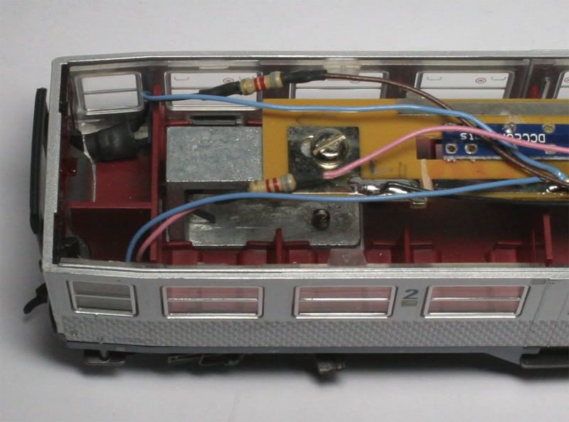
I have previously installed the DCCconcepts Flickerfree unit in a similar coach but this time I put the DCCconcepts circuit board on top of the Fleischmann Board and drilled holes in the Fleischmann Board to accommodate the LEDs
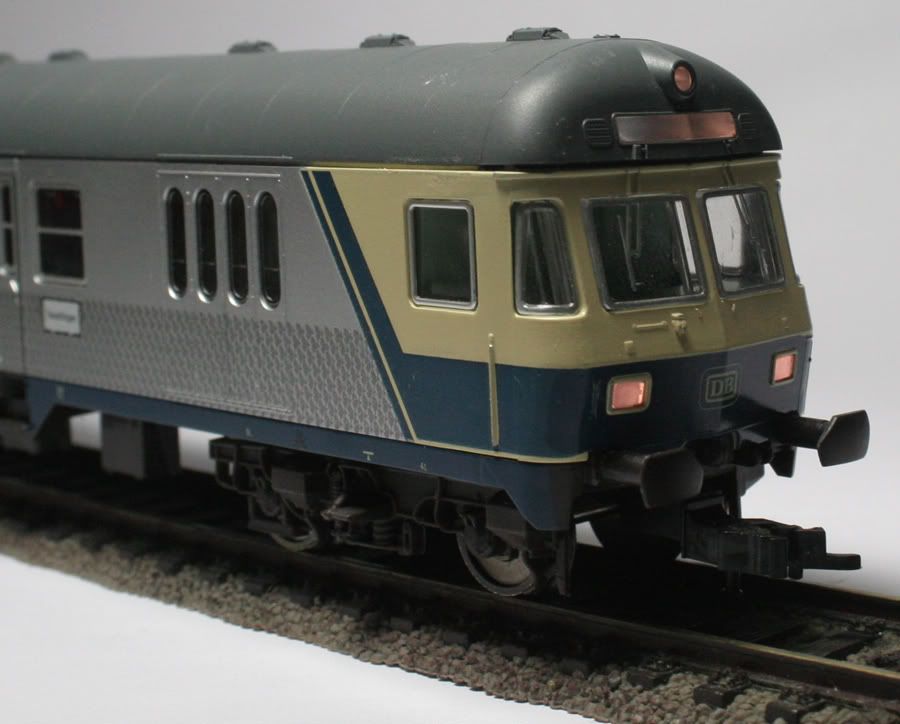
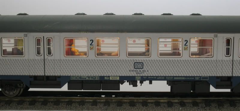
This control coach has power pickups on four wheels- two on one side of each bogie –Directional lighting at the cab end and provision for internal lighting.
The roof, as with all Fleischmann coaches, will come of when the clips are disengaged by pressing in the sides of the coach
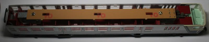
Mark out where the internal lighting LEDs will go. Previously I have put the lighting PCB under the Fleischmann PCB.
The Flicker free circuit board fits nicely between the original PCB board mounts
Drill holes for the LEDs to go through the PCB leaving the DCCconcepts board on top of the Fleischmann PCB
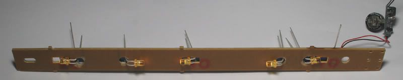
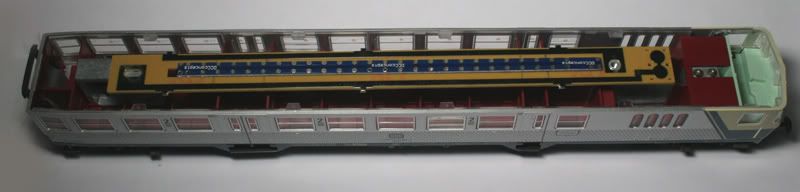
Above LEDs in place and being tested with the Flicker Free unit. I keep the LED’s tails in place until soldering has been finished. This draws heat away from the LED. The circuit board makes it easy to install the Prototype LEDs .Note I have bent them at 90 degrees to take them out of the line of site of the windows and give dispersion of light down the length of the coach
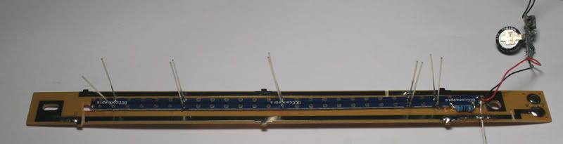
The DCCconcepts board stays in place with the LEDs tails going through the Fleischmann PCB
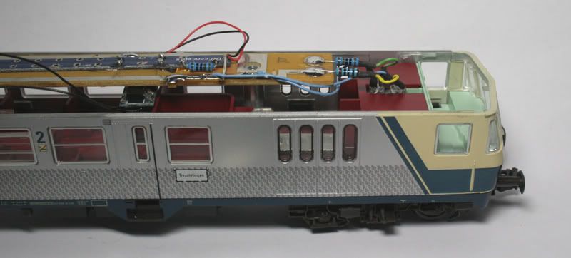
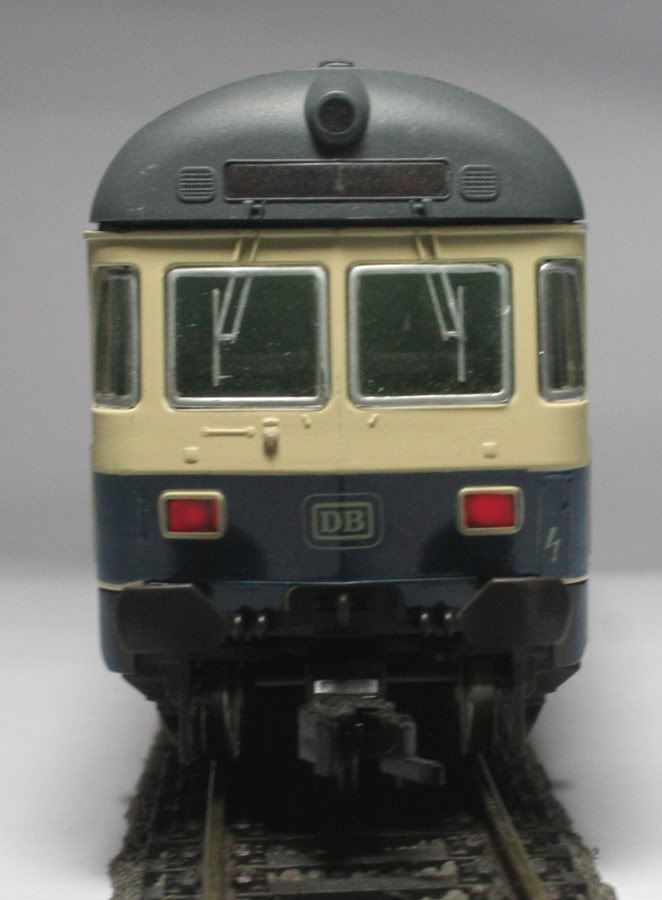
Above - Replace the mini globes with a Red and Warm White LED. The 3mm LEDs just fit snugly in the place of the original globes.A perfect spot for the Flicker Free unit in the Driver access way corridor
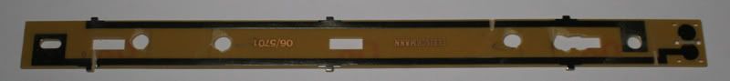
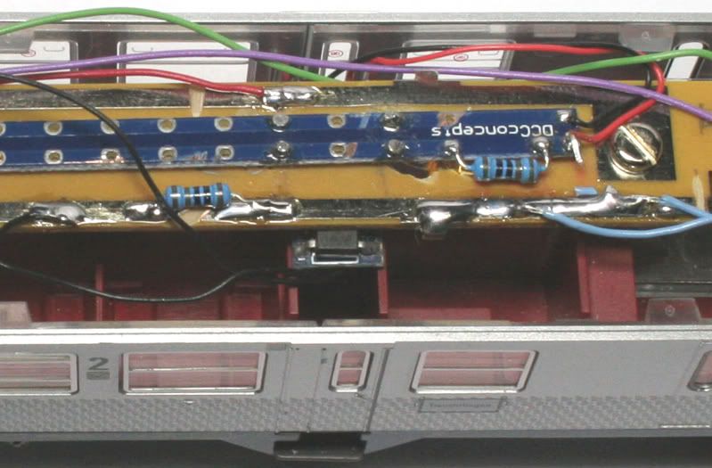
I cut the (Blue wire) PCB track separating the front lighting from the rest - allowing a variation in resistance to be used . Also added a 1k Ohm resistor across the cut and soldered the Blue wire from the decoder to the PCB track. This effectively gives 2 k Ohm for the Red LED and 1k1 Ohm for the White LED.
The Following picture shows the cut in the PCB board and the 1k Ohm resistor joining the two sections.
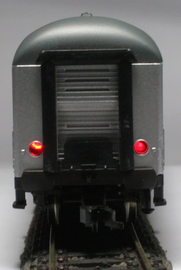
Two Red LEDs were added powered through 8.2 K Ohm resistors on the Purple and Brown function wires. Fitting snugly behind the Red lens of the coach’s tail warning lamps. As they are on separate functions, different programs can be used to have them Flash alternatively or stay on – the choice is there with these FL4 decoders.
This picture is taken in a poorly lit room with a time exposure enough to see detail inside the wagon.
No comments:
Post a Comment