Hi All,
Continuing on with conversions - this is the conversion for the BR53 - as I did 4 of these at once these are a couple of different models with a few differences but basically the same method is used.
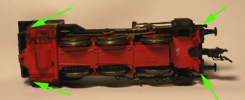
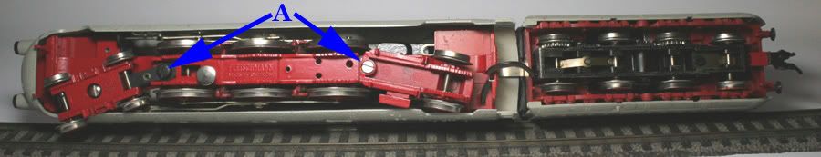
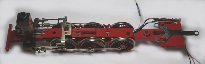
There are 4 clips holding the body to the chassis, the front two behind the buffers, the rear 2 along the cab, gently pry them open with a small screwdriver.
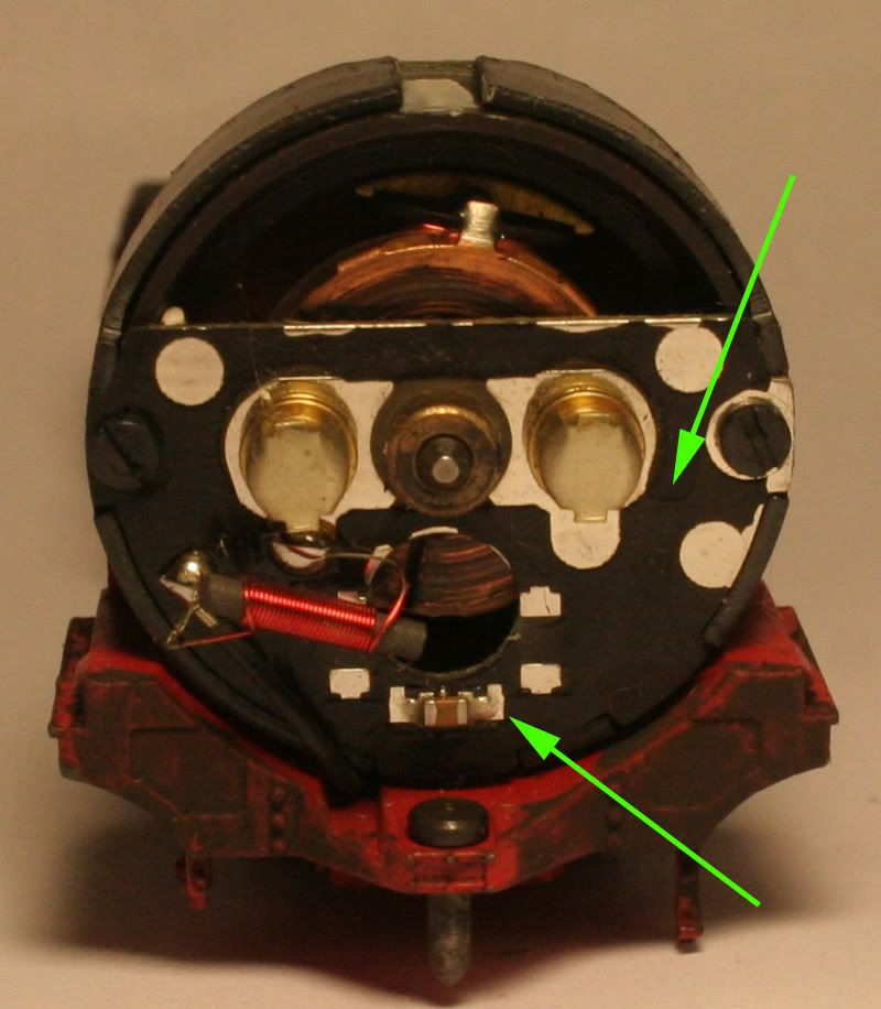
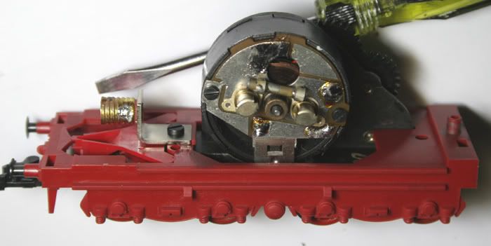
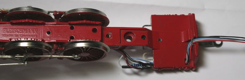
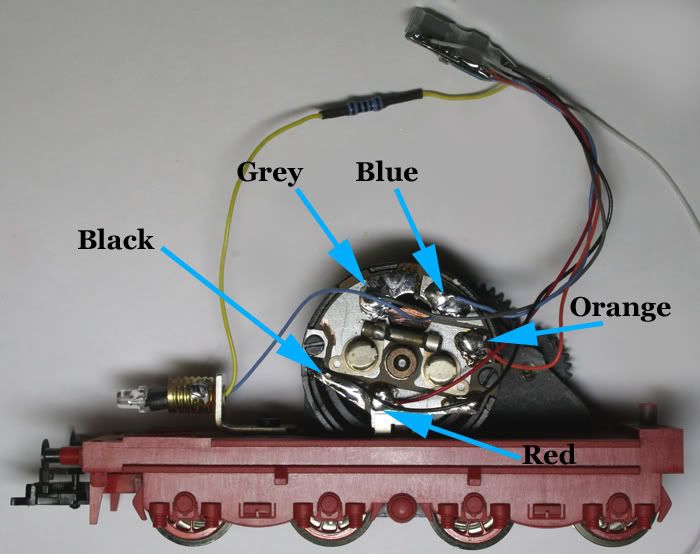
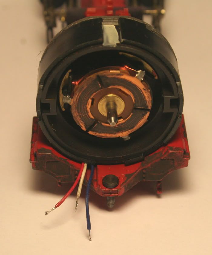
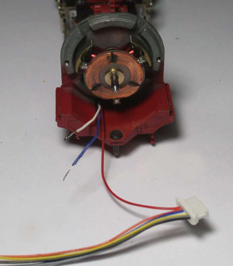
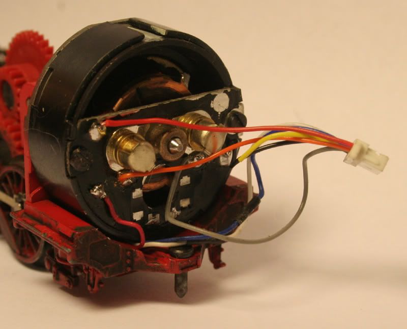
The picture above shows the view of the motor of the Locomotive, The above an earlier model – remove the Surface mount capacitor (arrowed) and the link connecting the chassis to the motor terminal (also arrowed). The below picture shows the later model with the NEM651 socket, you can plug a decoder straight into this or hardwire a decoder to this backplate. Replacing the backplate with Backplate #50 4732 is also an option.
Continuing on with conversions - this is the conversion for the BR53 - as I did 4 of these at once these are a couple of different models with a few differences but basically the same method is used.
There are 4 clips holding the body to the chassis, the front two behind the buffers, the rear 2 along the cab, gently pry them open with a small screwdriver.
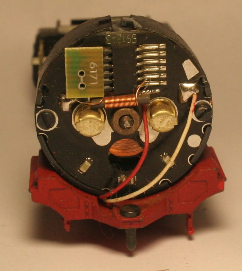
The picture above shows the view of the motor of the Locomotive, The above an earlier model – remove the Surface mount capacitor (arrowed) and the link connecting the chassis to the motor terminal (also arrowed). The below picture shows the later model with the NEM651 socket, you can plug a decoder straight into this or hardwire a decoder to this backplate. Replacing the backplate with Backplate #50 4732 is also an option.
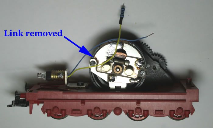
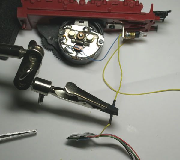
Remove the RF Choke and cut the link (Shown on the picture) on the motor shield (backplate).
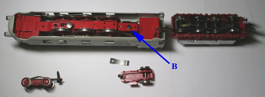
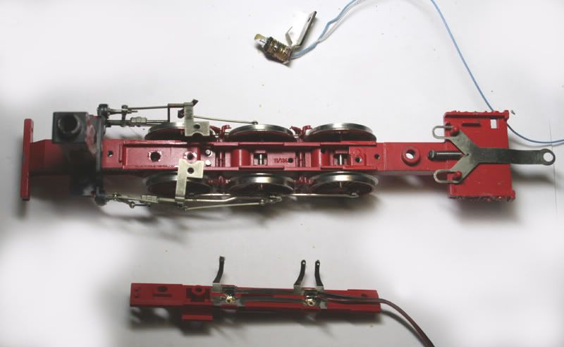
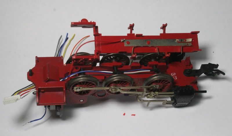
The wiring for the right hand rail pickups and the front light runs under the locomotive – to access this wiring remove the pickup assembly.
With a small screwdriver, loosen the tabs holding the assembly in place (arrowed right).
There are another two clips at the front of the locomotive that will require leverage and two in the middle between the wheels which will spring out when the assembly is pulled away from its mounts. The plastic is quite flexible so with care it will come out in one piece.
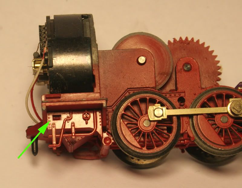
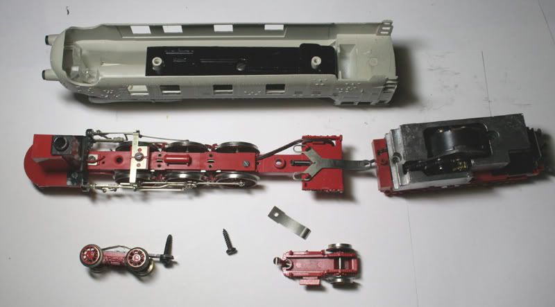
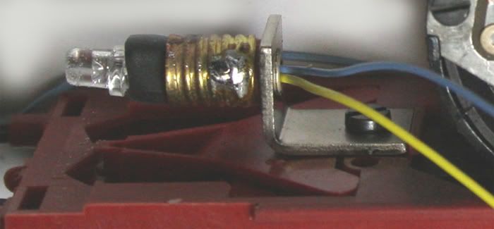
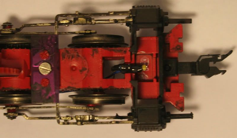
Above – This is the later model with separate power going to the front light (White wire). The early model has the contact for the front light electrically attached to the pickups (below). Cut the contact for the front lamp away. Replace the front lighting with an LED (small surface mount).
The wiring for the right hand rail pickups and the front light runs under the locomotive – to access this wiring remove the pickup assembly.
With a small screwdriver, loosen the tabs holding the assembly in place (arrowed right).
There are another two clips at the front of the locomotive that will require leverage and two in the middle between the wheels which will spring out when the assembly is pulled away from its mounts. The plastic is quite flexible so with care it will come out in one piece.
Above – This is the later model with separate power going to the front light (White wire). The early model has the contact for the front light electrically attached to the pickups (below). Cut the contact for the front lamp away. Replace the front lighting with an LED (small surface mount).
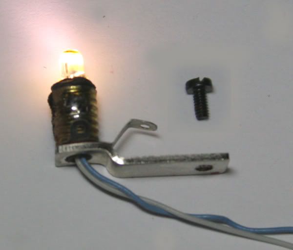
Warm White SMD LEDs – soldered directly to a 1 k Ohm 1/8 watt
resistor and blue wire making a small package taking up very little
room.
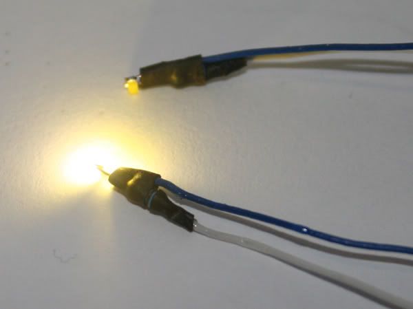
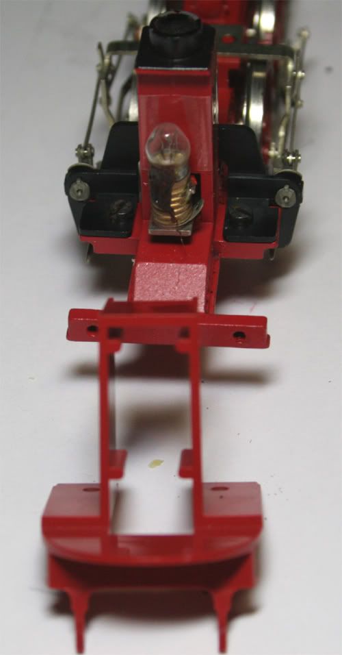
The lights ( after removing the originals) are put in place.
Glue the SMD in place of the original lamp with some CA glue running the wires down to the bottom of the chassis.
The LED faces straight up – the light will go directly into the light pipe from there and to the front buffer beam lanterns.
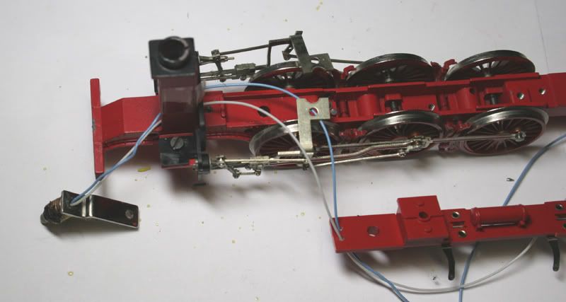
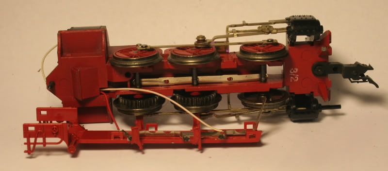
Below- the Blue and White wires from the LED running down the chassis.
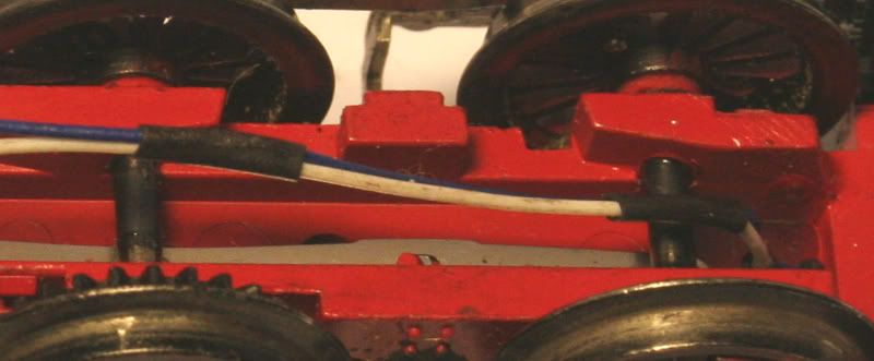
Note – Heat shrink protecting the wires where they pass over the axles.
There is quite a bit of room over the axles for the wires but as they may rub on the axles a little bit of heat-shrink will give added protection against short circuits.
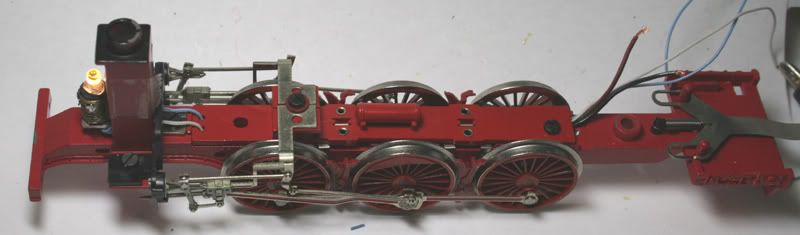
Wiring from the Harness
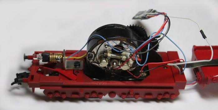
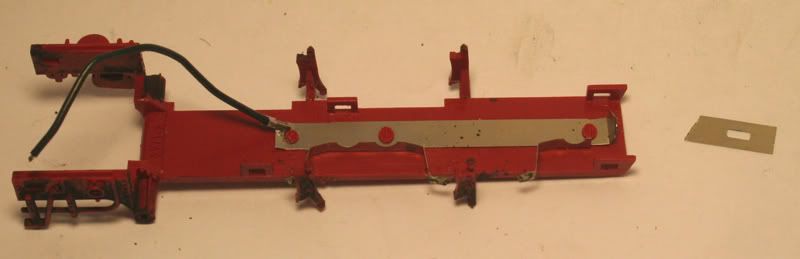
The preceding pictures show the pickup and the path of the wires through the chassis and out under the motor.
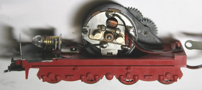
Top – the older model and directly above- the newer model with the red wire from the harness soldered directly to the pickup. The motors outer casing and ring magnet removed for easier access to the groove that the wiring is located in. The commutator on the motor is also in need of a clean.

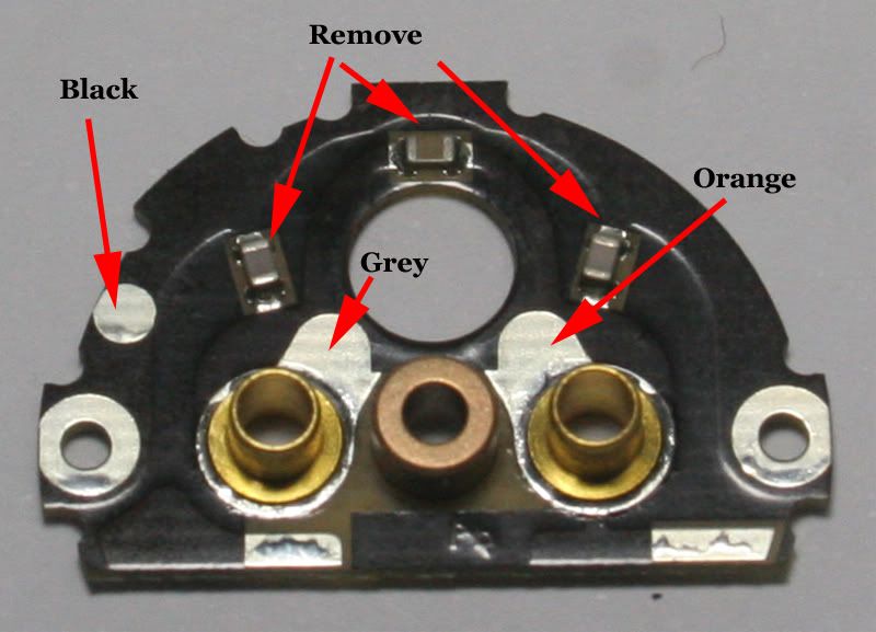
The Standard 50 4732 Motor Backplate as it comes new from the factory. This will fit any of the motors with two mounting screws, unless they have pick ups attached to the backplate.
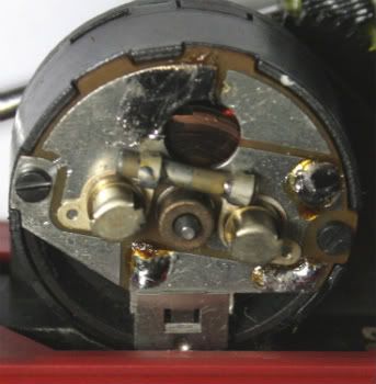
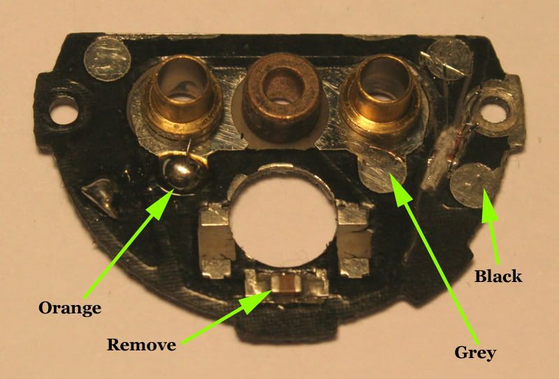
Remove the SMD Capacitors as marked. These are for RF suppression and are not required with a decoder in the motor circuit, they will also interfere with the decoders BEMF motor control.
The preceding pictures show the pickup and the path of the wires through the chassis and out under the motor.
Top – the older model and directly above- the newer model with the red wire from the harness soldered directly to the pickup. The motors outer casing and ring magnet removed for easier access to the groove that the wiring is located in. The commutator on the motor is also in need of a clean.
Modifications to the Original back-plate of the older model - Showing
the place the link (electrically bonding the chassis to the motor
terminal) is cut as well
The Standard 50 4732 Motor Backplate as it comes new from the factory. This will fit any of the motors with two mounting screws, unless they have pick ups attached to the backplate.
Remove the SMD Capacitors as marked. These are for RF suppression and are not required with a decoder in the motor circuit, they will also interfere with the decoders BEMF motor control.
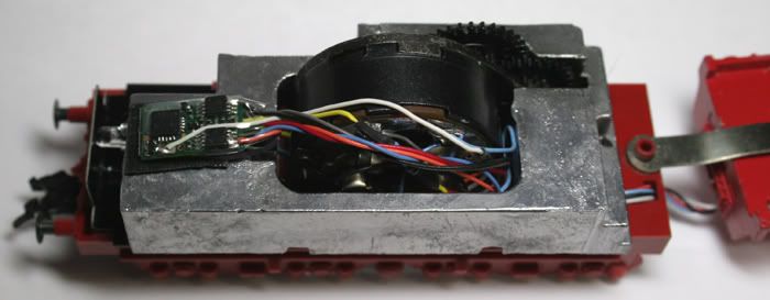
Decoder harness soldered in place
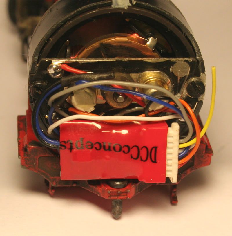
Richard put the label upside down on this one

|
|
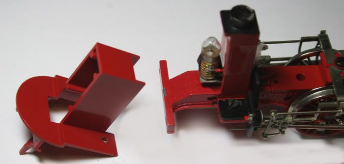
Paint helps disguise the decoder.
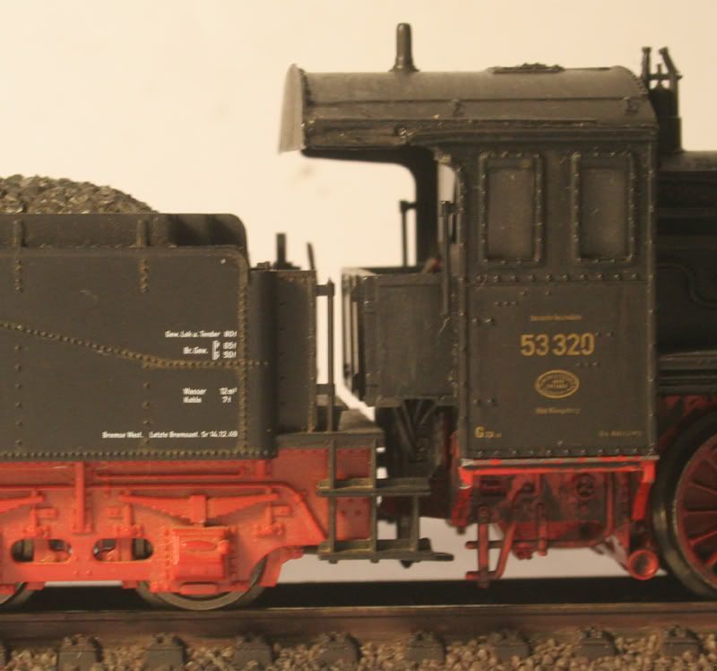
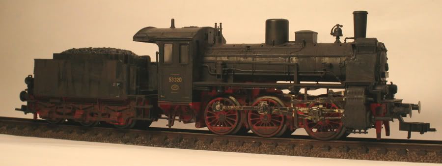
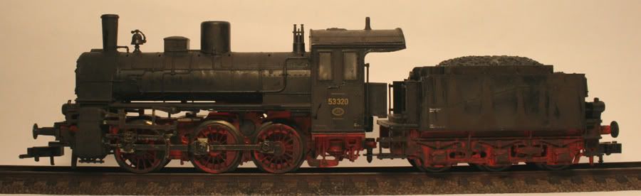
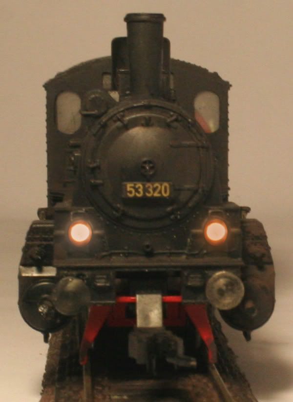
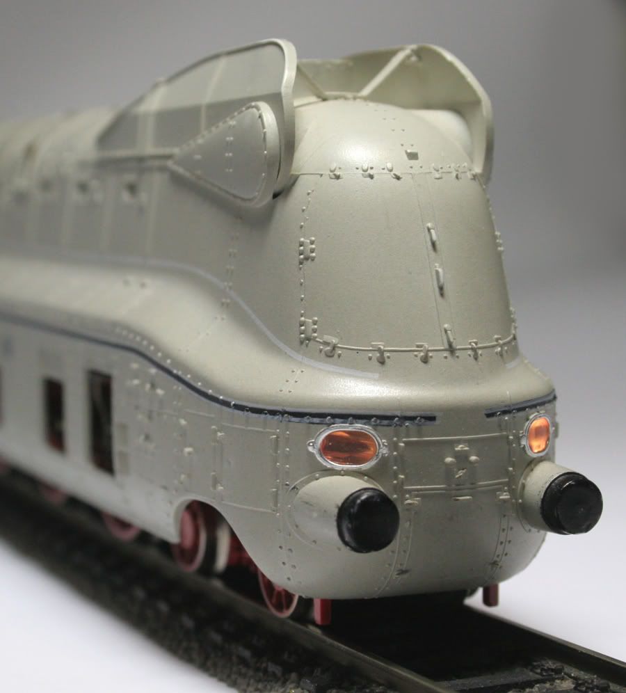
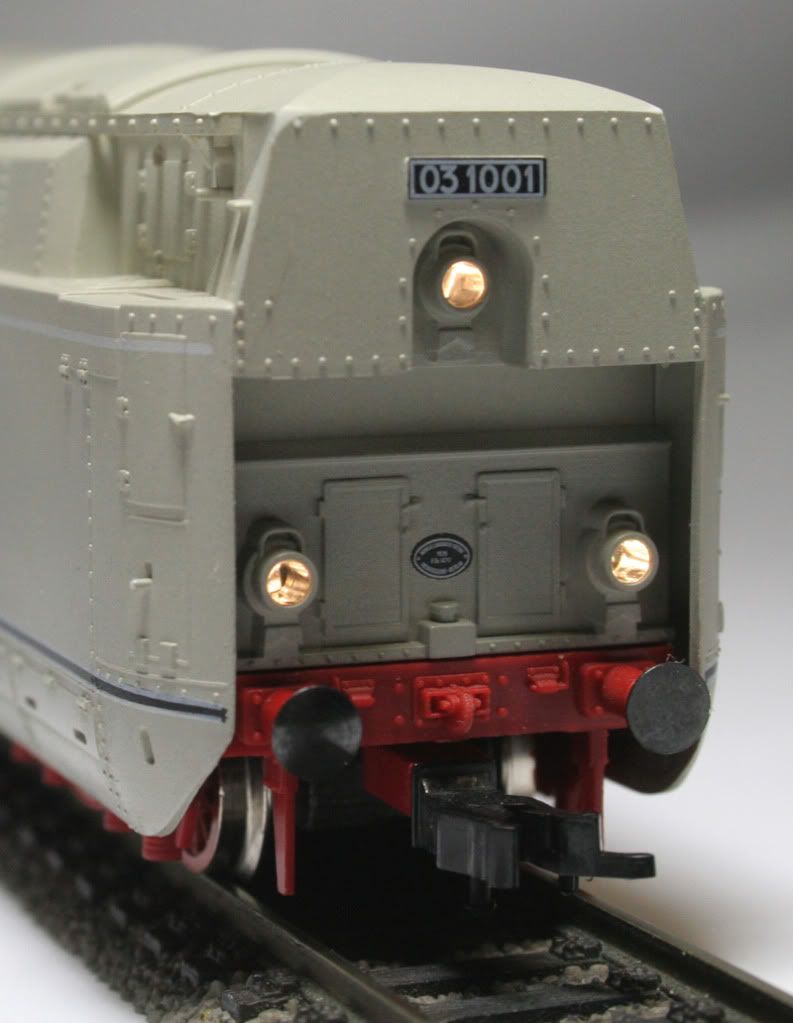
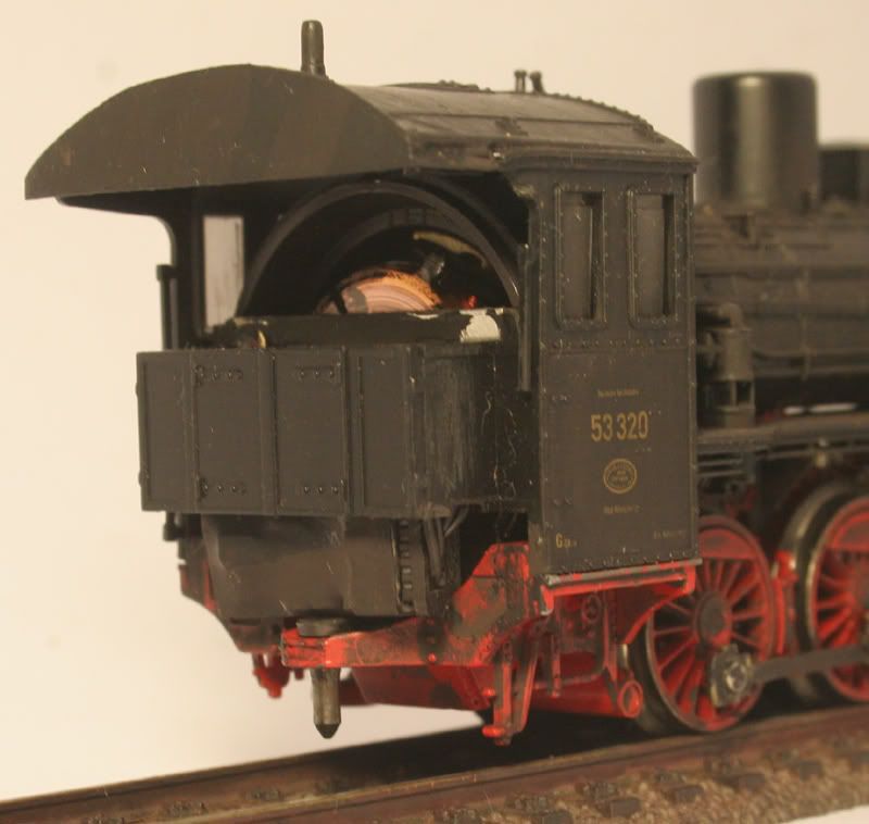
Some pictures of the weathered BR53 ( Prussian P4.3) That I have modified a bit and weathered